SPUR GEARS
Parallel Shaft ApplicationsReliability from Steel, Cast Iron and Brass
More Cost Effective, Quieter Running and Corrosion-Resistant Operation from NonMetallic Options
Higher Load Carrying Capacity with 20?PA (Pressure Angle )
Higher Contact Ratio for a Smoother,
Quieter Operation with 14-1/2?P
Selections From Stock
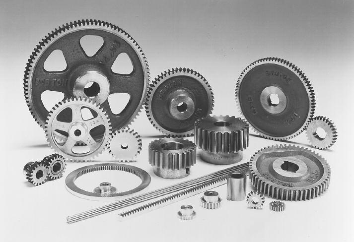
Pinions and Gears (Steel, Cast Iron, Brass, Non-Metallic)
Change Gears (Steel or Cast Iron)
Stem Pinions (Steel)
Drawn Pinion Wire (Brass, Steel)
Rack (Steel, Nylon)
Internal (Brass)
Diametral Pitch 64 DP to 3 DP
Pitch Diameter .208" to 36.000"
Diametral Pitch System Standardized on Stock Gears
14-1/2?and 20?Pressure Angle
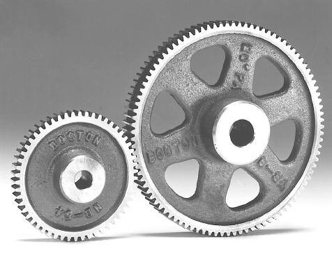
Boston spur gears are designed to transmit motion and power between parallel shafts. Configurations include spur, rack, pinion wire, stem pinions and internal gears; most with a selection of bores, keyways and set screws. Fine-pitch gears are available in plastic, brass, stainless steel and steel. Heavier pitch spurs are available in steel and cast iron. Styles include plain, web, web with lightening holes or spoked. Change gears have consecutive numbers of teeth for a variety of ratios.
 Boston Gear manufactures both 14-1/2?and 20?PA, involute, full dep
system gears. While 20?PA is generally recognized as having higher loa
carrying capacity, 14-1/2?PA gears have extensive use. The lower pressur
angle results in less change in backlash due to center distance variation
and concentricity errors. It also provides a higher contact ratio and is
consequently a smoother, quieter operation provided that the undercut of
the teeth is not present.
Boston Gear manufactures both 14-1/2?and 20?PA, involute, full dep
system gears. While 20?PA is generally recognized as having higher loa
carrying capacity, 14-1/2?PA gears have extensive use. The lower pressur
angle results in less change in backlash due to center distance variation
and concentricity errors. It also provides a higher contact ratio and is
consequently a smoother, quieter operation provided that the undercut of
the teeth is not present.Boston spur gears are designed to transmit motion or power between parallel shafts. Configurations include spur, rack, pinion wire, stem pinions and internal gears; most with a selection of bores, keyways andsetscrews. Styles include plain, web, web with lightening holes or spoked. Change gears have consecutive numbers of teeth for reduction uses.
Boston fine-pitch spur gears are available in Delrin and Brass. Configurations include spur, rack, pinion wire and internal gears; most with a selection of bores, keyways, and setscrews. Styles include plain, web with lightening holes or spoked.
SELECTION PROCEDURE
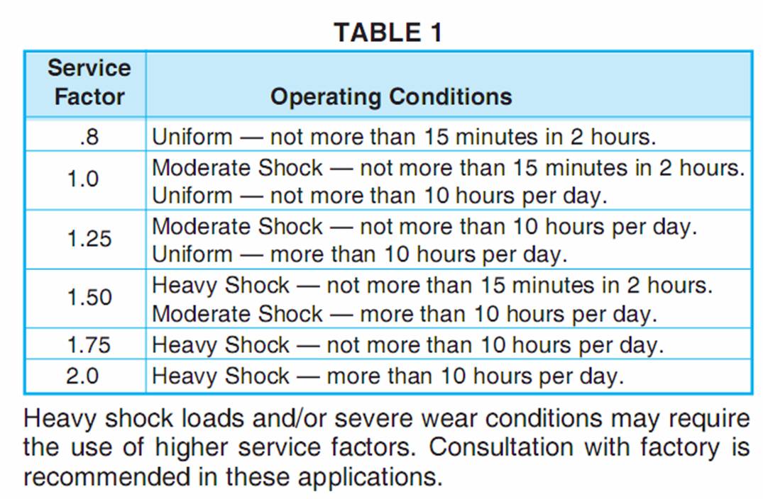
1.Determine service factor.a.Using application Classification Chart, pages 152153, determine service factor or
b.With knowledge of operating conditions and load classification, select service factor from Table 1 below.
Design HP = Application Load X Service Factor (Table 1)
3.Select spur gear pinion with horsepower capacity equal to
(or greater than) design horsepower determined in Step 2.
14-1/2?Pressure Angle Spur Gears?TM)Page 38 to Page 4
20?Pressure Angle Spur Gears?TM) Page 46 to Page 54.Select a driven spur gear with a catalog rating equal to or greater than the horsepower determined in Step 2. All ratings are predicated on gears properly lubricated and maintained.
SELECTION HINTS
A.Select pinion having pitch diameter at least twice the
shaft diameter.B.Pinion number of teeth should be greater than 16 for 14-1/2?PA and 13 for 20?PA to avoid excessive unde cutting.
C.For tooth numbers or RPMs not on Chart, interpolation of horsepower is adequate.
D.Pitchline velocities above 1000 FPM are not recommended for metallic spur gears. The Selection Chart reflects this in the lack of ratings for larger numbers of teeth at higher RPM/s. Ratings to the right of heavy lin are not recommended, as suggested maximum velocity is exceeded, and should be used for interpolation purposes only.


